STATUS: FIELD VALIDATED · REV: C4.0 · DATA SOURCE: REAL-WORLD · RUNTIME: 12 MONTHS

Built. Broken. Rebuilt.
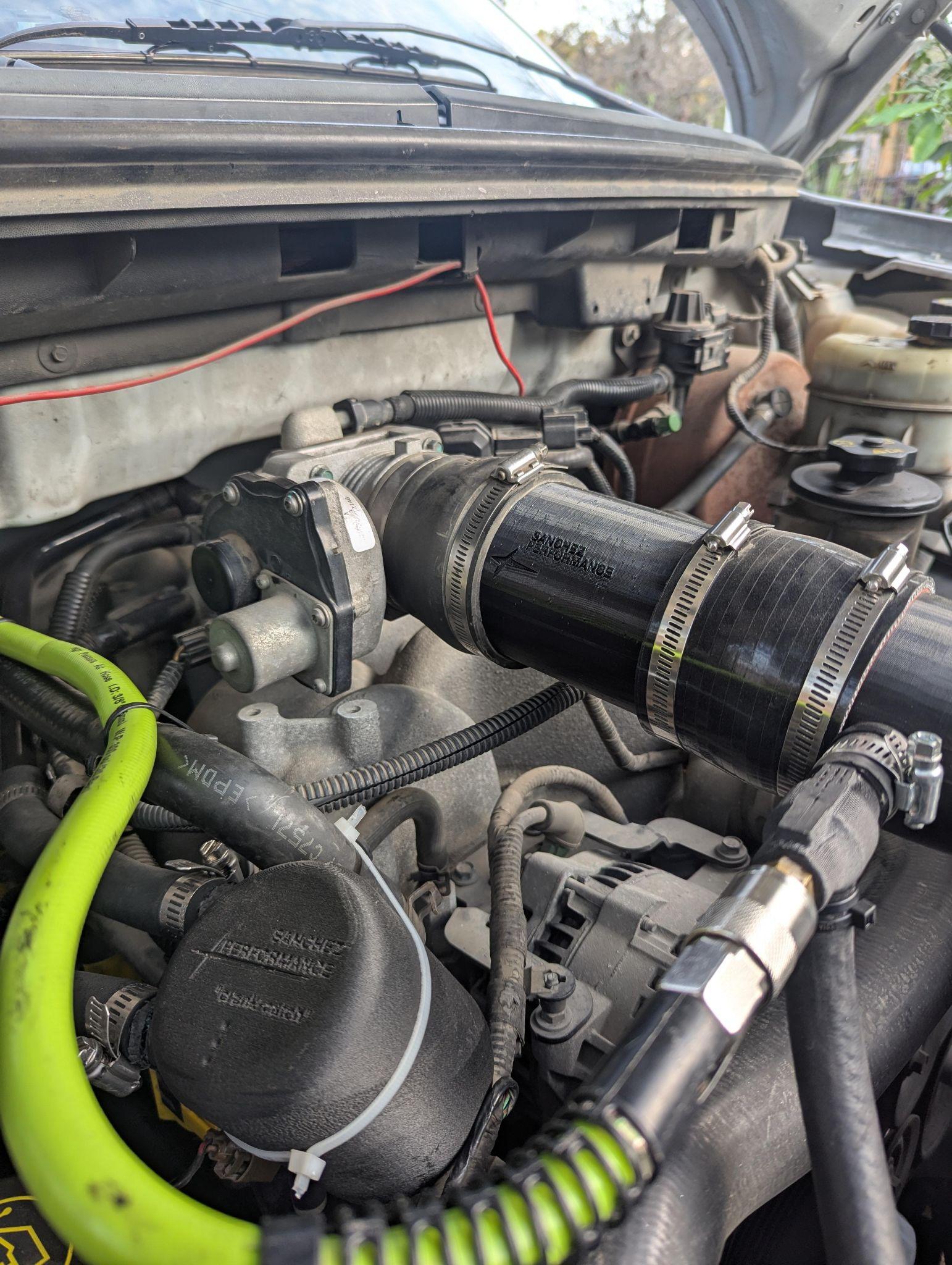
Every Sanchez Performance product begins as a problem the market hasn't solved correctly. What follows is iteration — real materials, real failure modes, real engine bays. Not simulated. Not speculative.
"Failure is data. Data is king."
STATUS: RELEASED · BATCH MODEL: BUILD-TO-ORDER · ORIGIN: SANCHEZ LABS R&D
Current Product Catalog
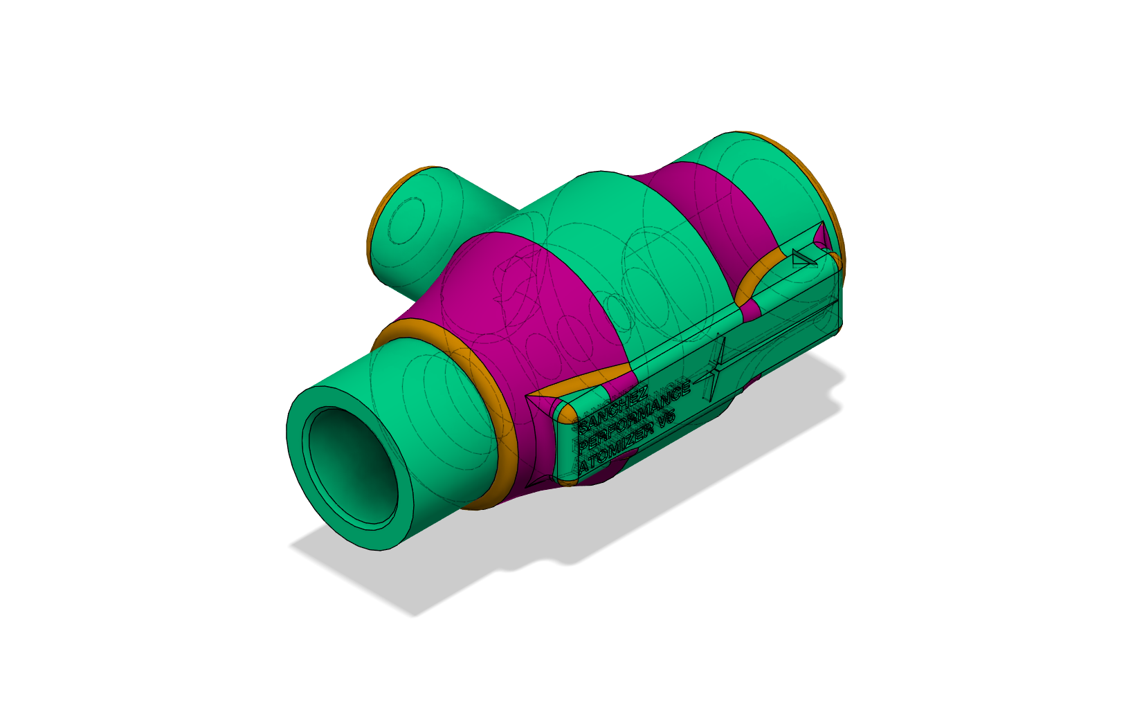
PRESION Catch Can
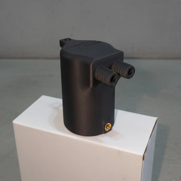
Additively manufactured crankcase separator with internal geometry subtractive machining cannot produce. PPA-CF body, nanoceramic sealed, unibody hose barb design.
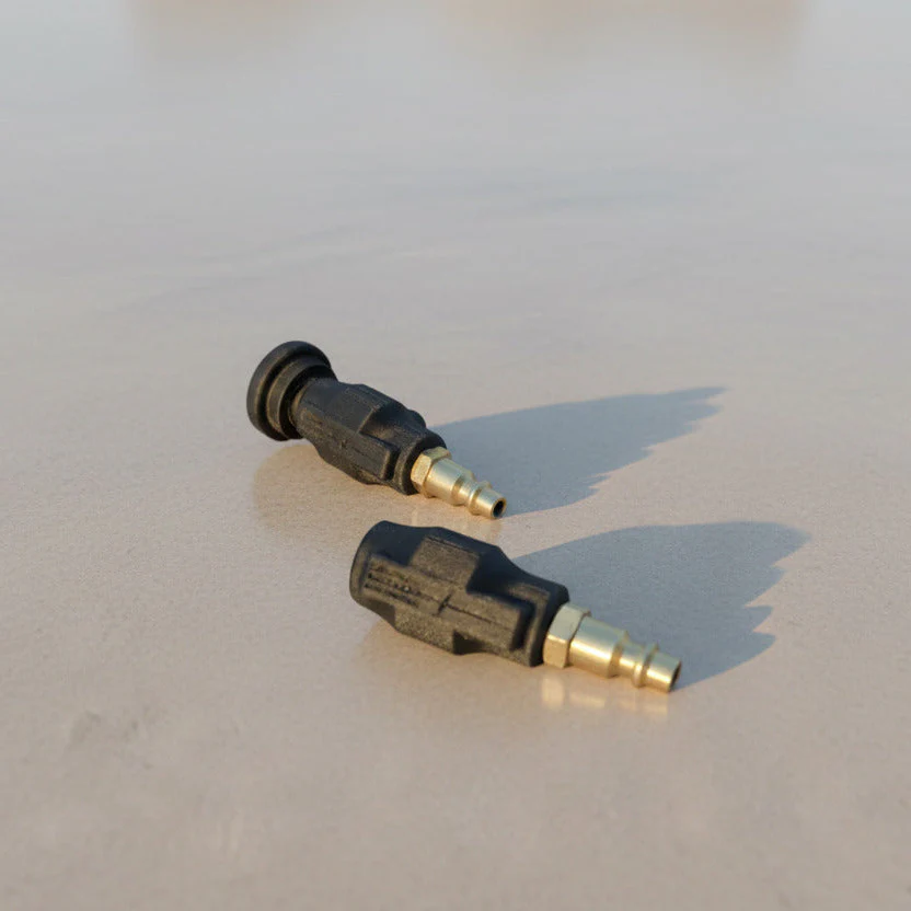
ATOMIZER Nozzles
Near-sonic venturi water/methanol injection. Pump-free. $3 in materials vs. $130 retail. Choked flow at the orifice produces superior atomization without complex wiring.
PRODUCT 01 · STATUS: VALIDATED · DOMAIN: CRANKCASE MANAGEMENT · REV: C4.0
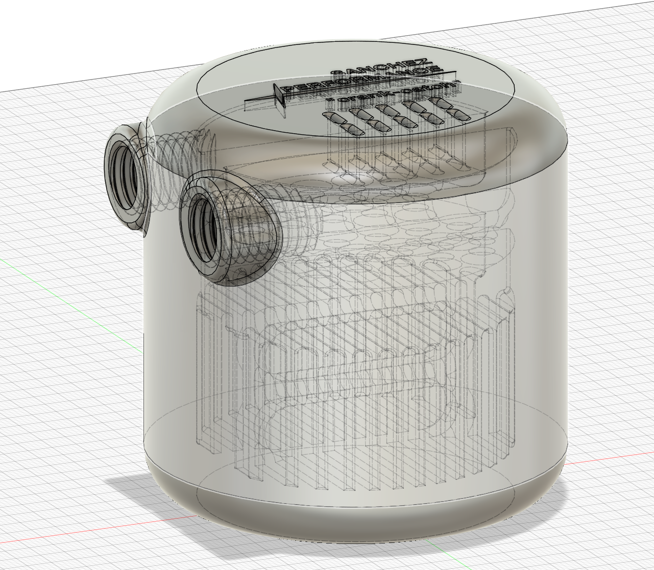
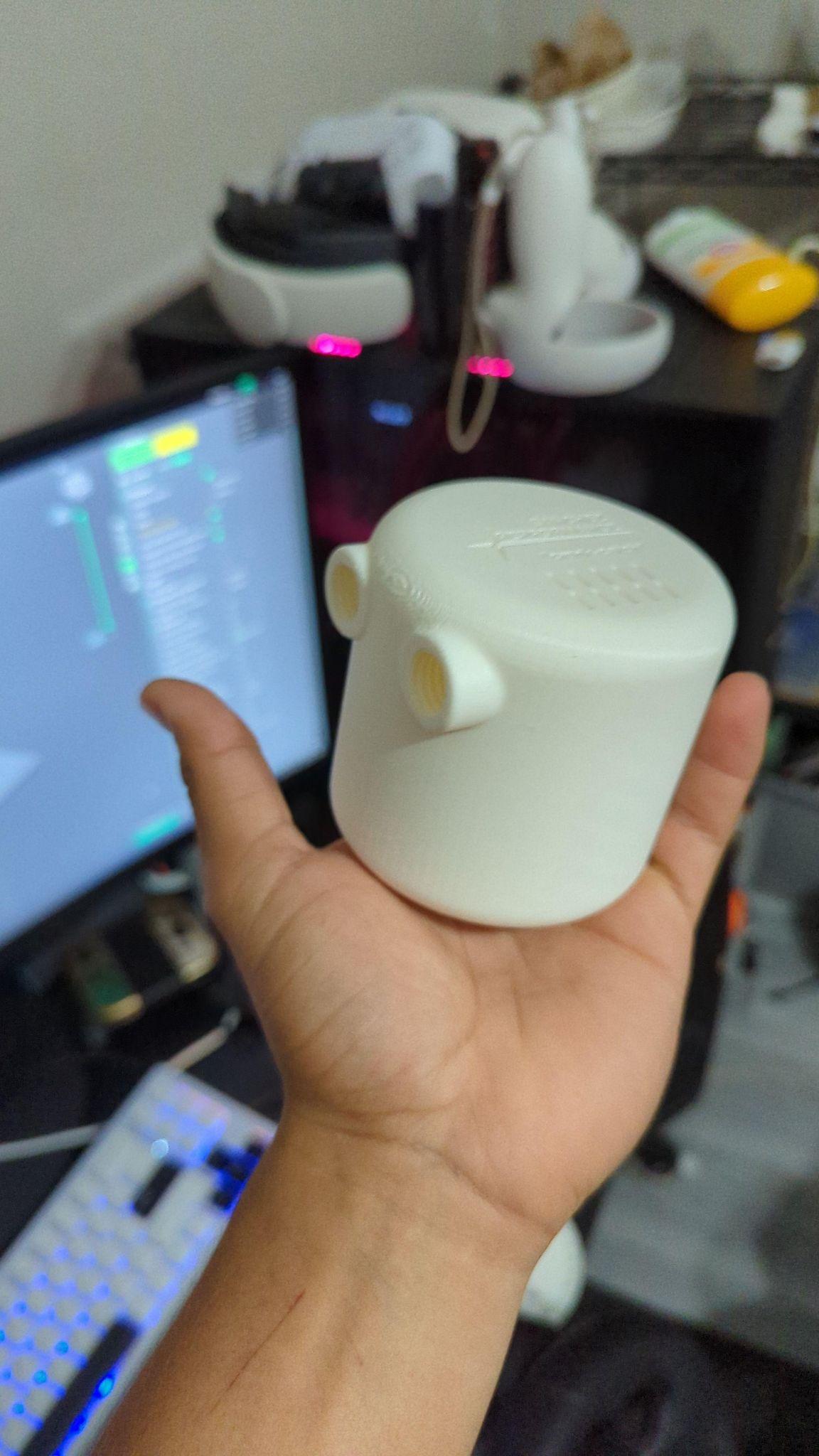
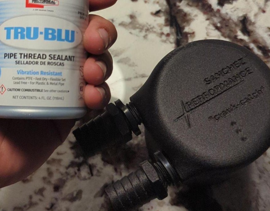
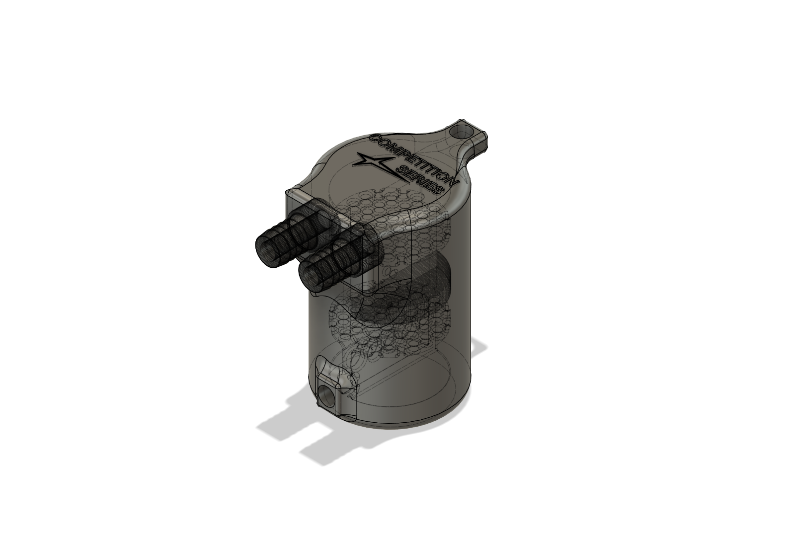
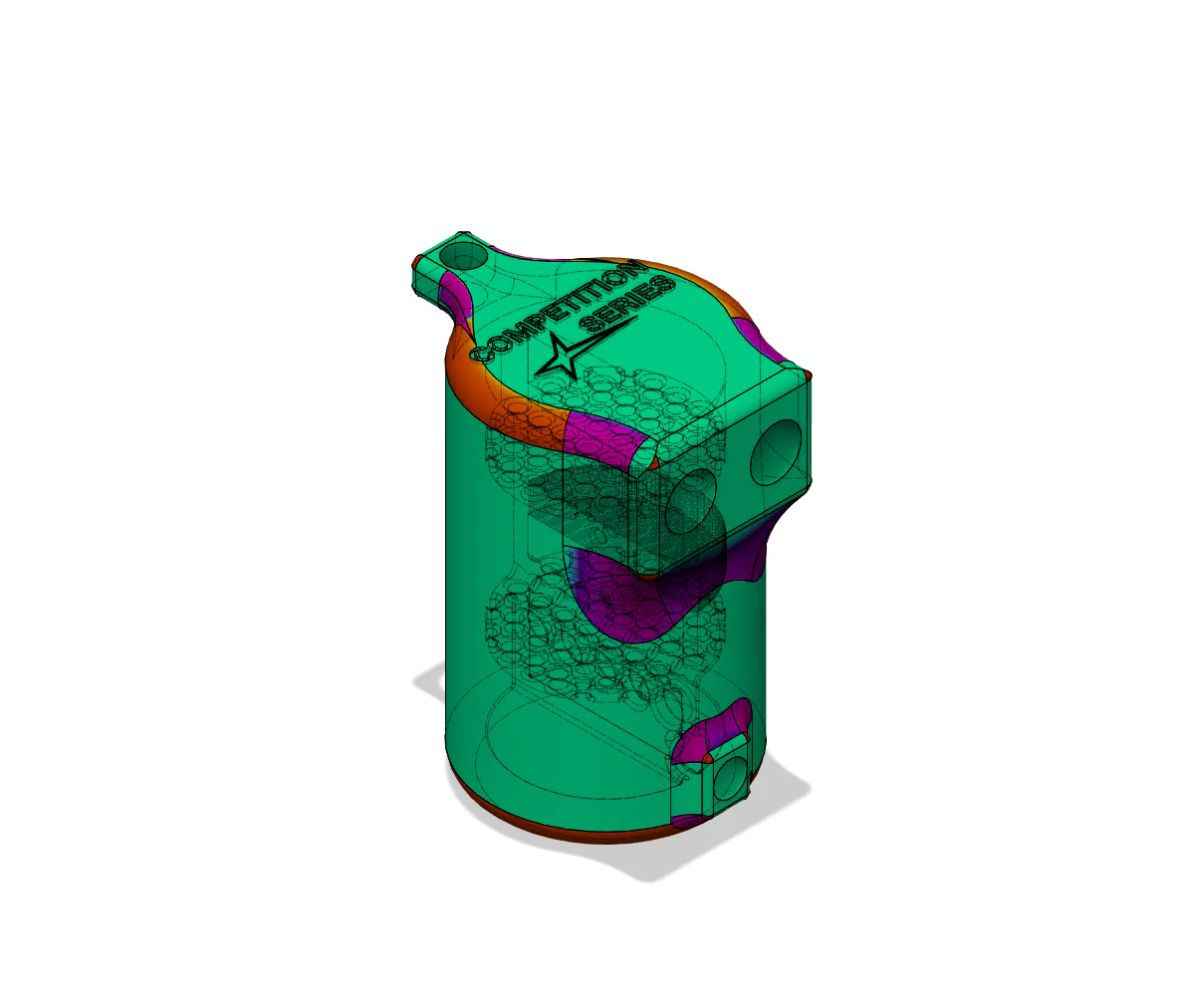
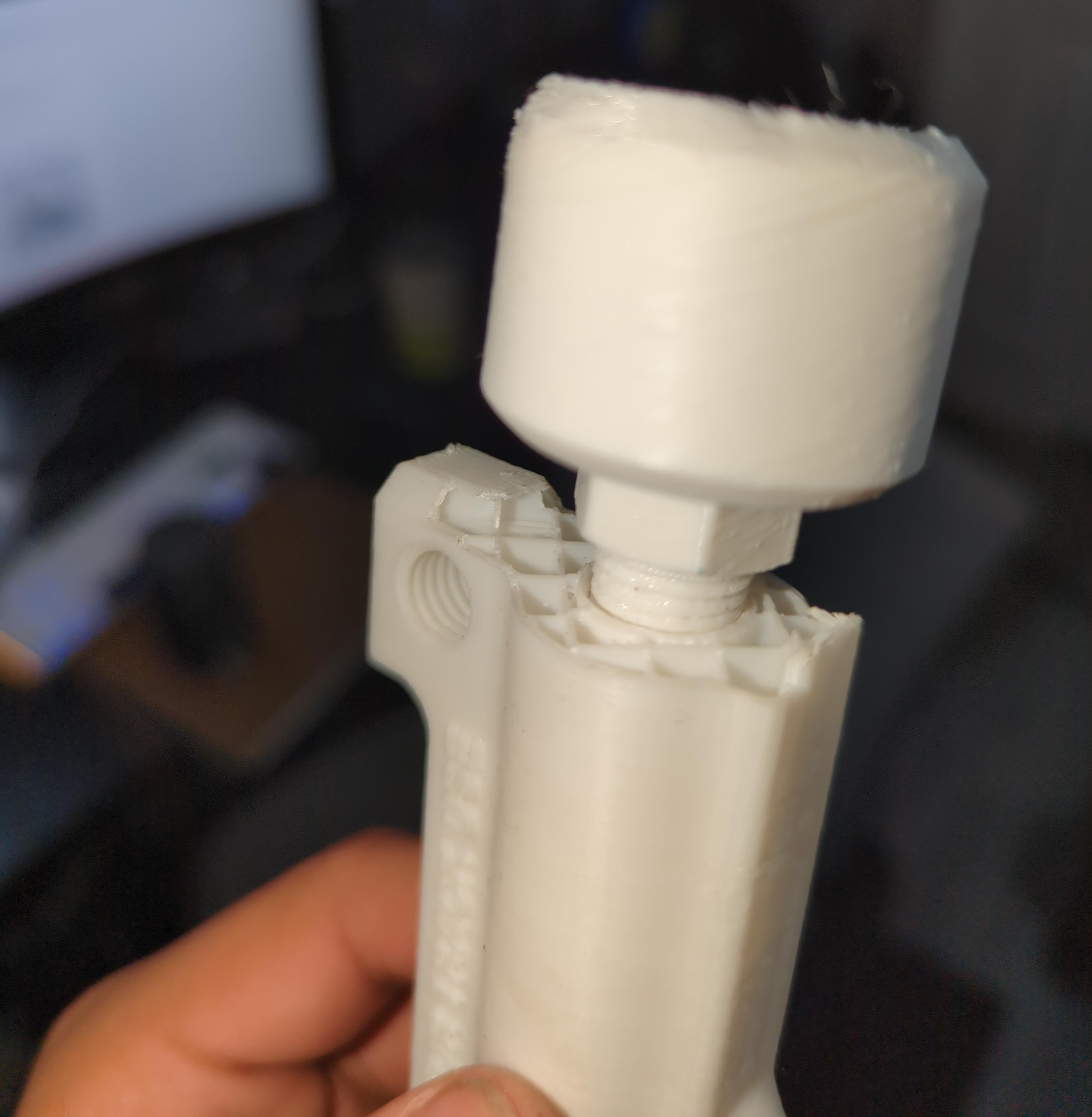
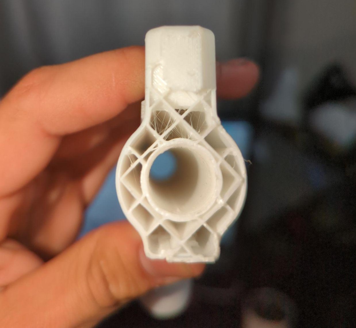
PRESION Catch Can
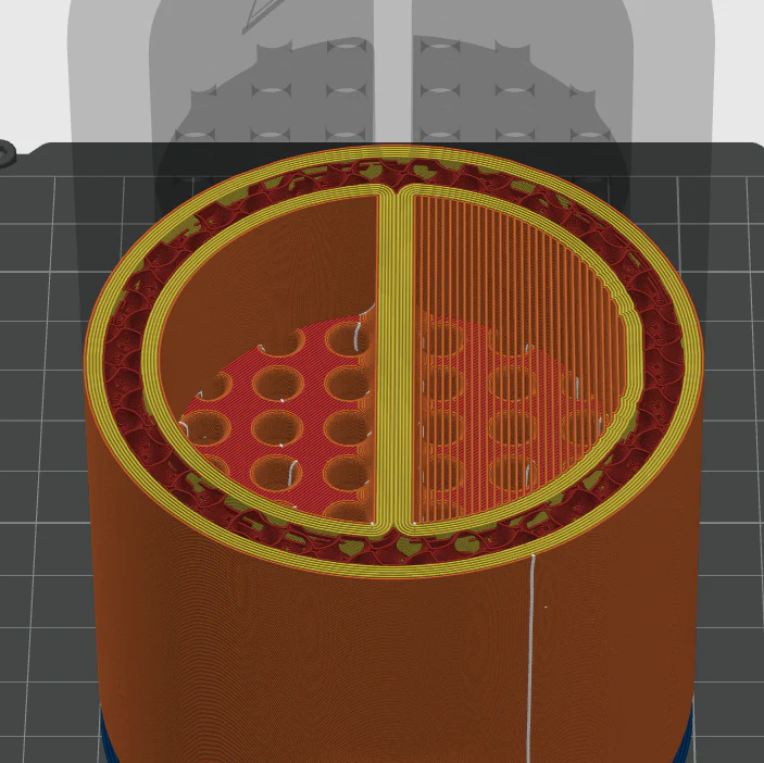
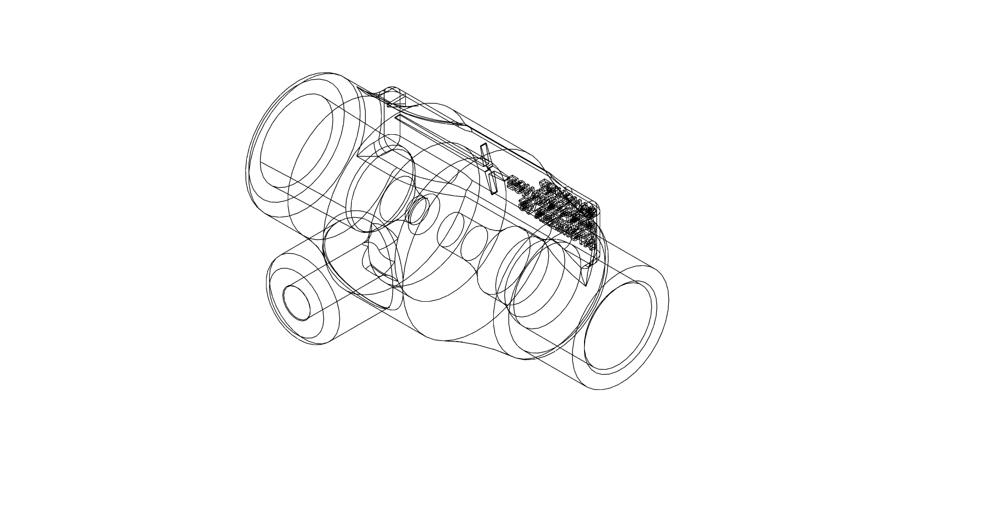
The geometry inside a traditional catch can is limited by what a drill bit can reach.
Ours isn't.
High-performance and forced induction engines generate blow-by — combustion gases that escape past piston rings, carrying oil mist and fuel vapor into the intake. Unmanaged, this contaminates throttle bodies, lowers octane locally, and accelerates carbon buildup on valves.
Traditional catch cans use simple baffles or mesh filters achievable with standard machining. They work until they don't — under high CFM pulses, separation breaks down, flow backs up, or maintenance intervals become impractical.
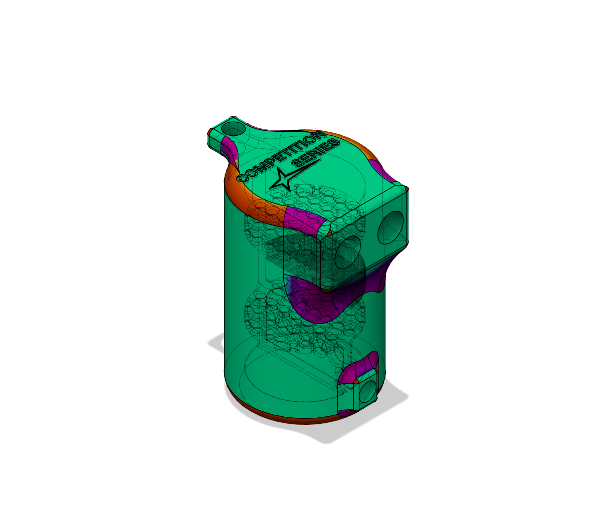
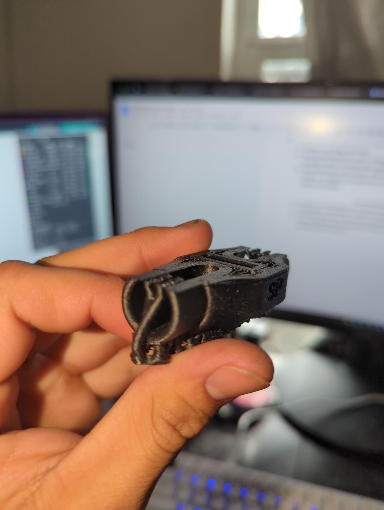
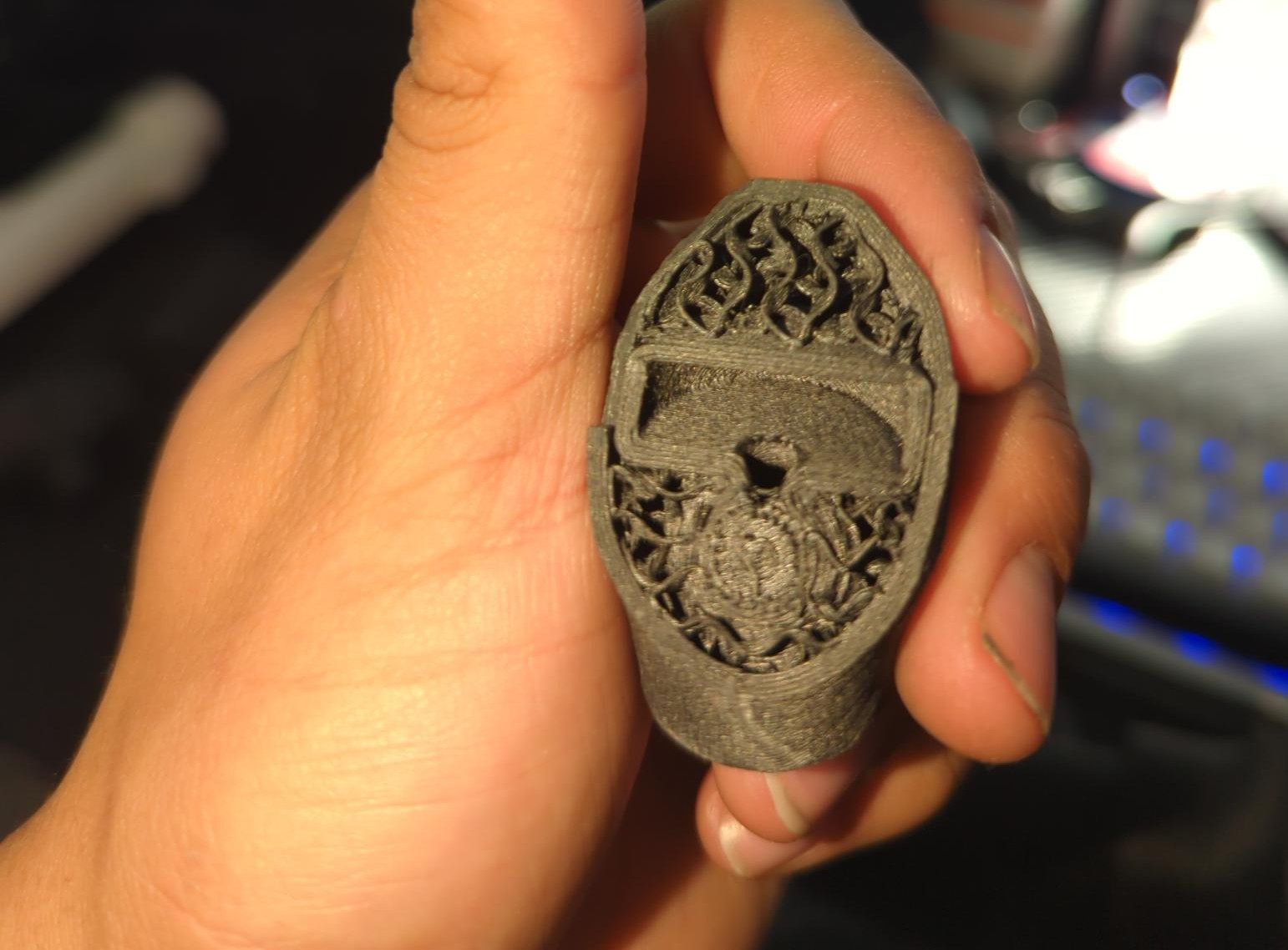
The PRESION was designed around a different constraint: use additive manufacturing to produce internal geometry that machining fundamentally cannot replicate, then optimize that geometry for maximum condensing surface area and flow efficiency simultaneously.
Final Specification
| Material | PPA-CF (carbon fiber reinforced polyphthalamide) |
| Coating | Nanoceramic (polysilazane) — vapor absorption resistance, surface finish |
| Design | Unibody — print-in-place hose barbs, no thread failure points |
| Baffling | Multi-stage, high-CFM tuned, anti-re-entrainment geometry |
| Serviceability | 10mm drain plug |
| Fitment | Universal — ⅜" to ¾" hose |
| Mass | ~300g |
| Heat validation | 4+ weeks continuous engine bay heat soak |
| Runtime data | 12 months on-vehicle — oil mist capture confirmed |
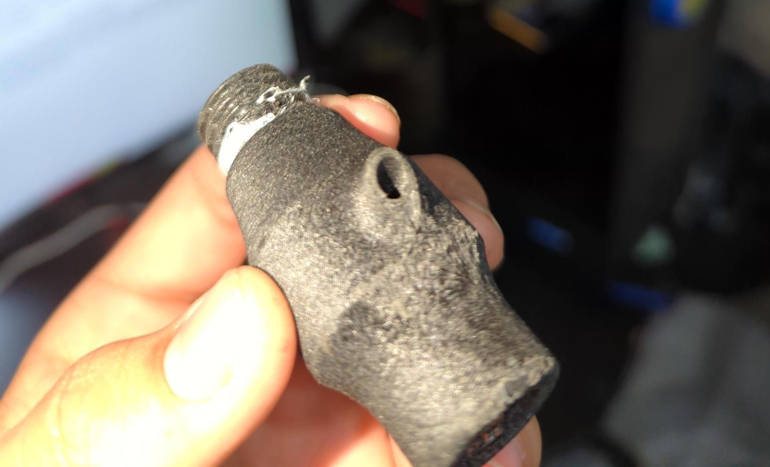
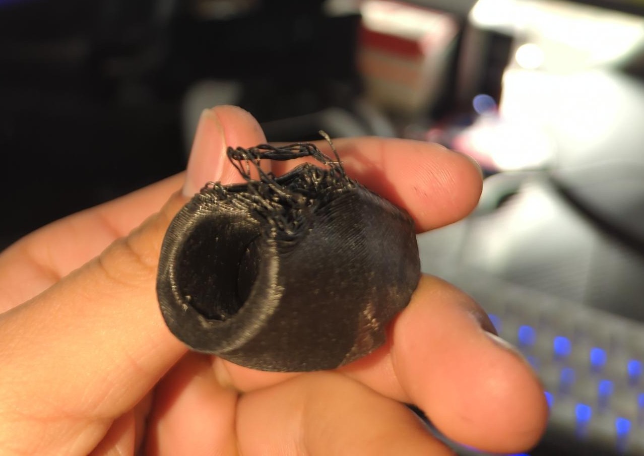
First Generation — Proof of Concept
Problems
- PLA — chemical resistance inadequate for production
- Baffle geometry ineffective at high CFM — mesh too coarse, oil carryover observed
- Threads and ports not evaluated for long-term torque
Confirmed
- Additive manufacturing enables rapid iteration of internal geometry
- Multi-port, multi-baffle design feasible in compact housing
Second Generation — Geometry Optimization
Problems
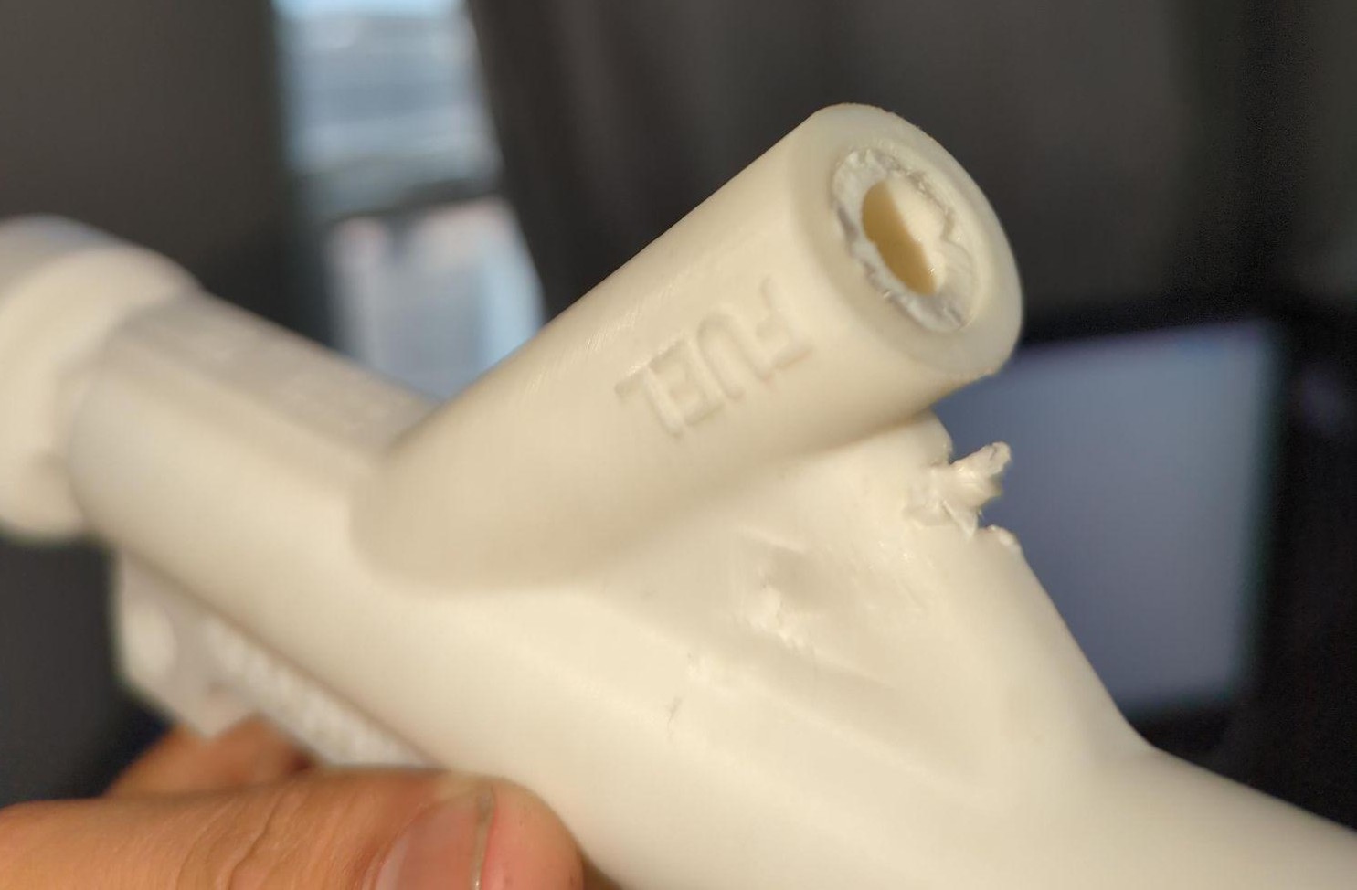
- Port insert cracked under hose fitting torque
- Perpendicular vanes too restrictive at high CFM — bypass under pulsing blow-by
Confirmed
- Baffle angle and spacing directly influence oil capture efficiency
- Internal channels tunable to prevent carryover even in CF-reinforced nylon
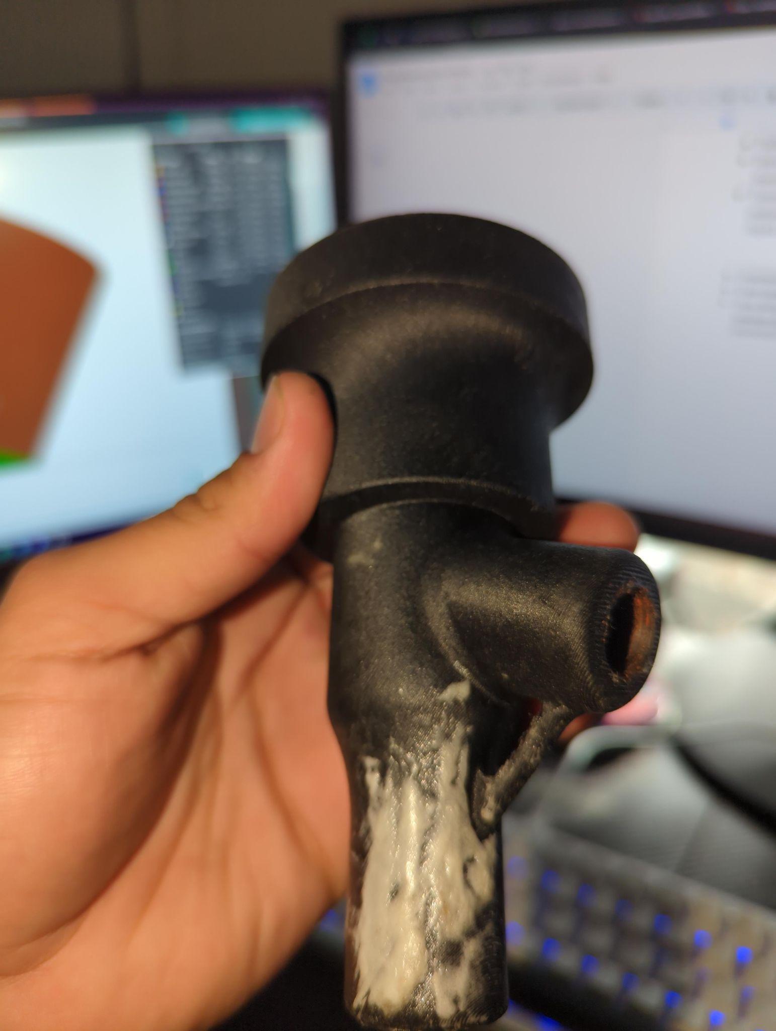
Third Generation — Engine-Ready
Changes
- Print-in-place hose barbs — eliminated thread failure points entirely, unibody construction
- Nanoceramic (polysilazane) impregnation — sealed against vapor absorption, improved surface finish
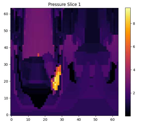
- Internal channels re-tuned for high-CFM pulses — droplet re-entrainment minimized
- 10mm drain plug added for serviceability
Validated
- 4+ weeks continuous engine bay heat soak — no deformation, no failure
- Universal fitment ⅜" to ¾" hose — no adapter required
- High separation efficiency under pulsating blow-by without backpressure
- 12 months real-vehicle runtime — currently in service
Fourth Generation — Current Production
Changes
- Switched to PA12-CF — deliberately overextruded to force inter-layer fusion and seal micro-pore pathways without nanoceramic reliance
- Overextrusion strategy increases wall density and cross-layer bonding — stronger part, better seal, same geometry
- Microporosity near-eliminated as a material property, not a post-process fix
Result
- Sealing dramatically improved over all previous generations — intrinsic to the print, not applied
- Part strength increased — overextrusion increases inter-layer contact area and load distribution
- Reduced dependency on post-processing — fewer steps between print and deployment
PRODUCT 02 · STATUS: VALIDATED · DOMAIN: WATER/METHANOL INJECTION · REV: D4.0
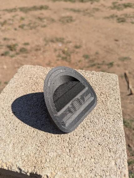
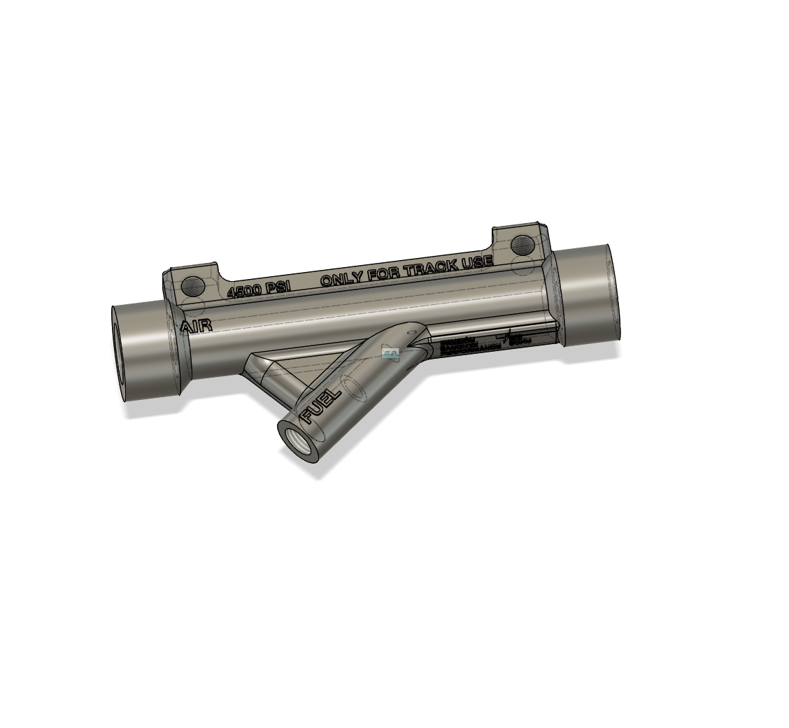
ATOMIZER Nozzles
The market charges $130 for a pump-dependent nozzle.
We removed the pump entirely.
Water/methanol injection lowers charge air temperatures in forced induction engines — critical when compressed intake air rises with it. Traditional systems rely on electrically driven pumps with PWM control logic, complex wiring, and multiple failure points.
The ATOMIZER eliminates the pump through venturi-based vacuum ejection geometry. Regulated compressed air — 25 to 75 PSI from an existing tank — creates a near-sonic choked flow at a precision orifice. The resulting pressure differential draws and atomizes fluid without a pump, without wiring complexity, without the failure modes.
Total cost to manufacture: approximately $3 in filament and fittings. Retail equivalents: $100–130. Atomization quality: superior, due to choked flow characteristics at the orifice producing finer droplet distribution than pump-driven alternatives.
Final Specification
| Material | PPA-CF (Polythalamide-CF) — heat and chemical resistance |
| Coating | Nanoceramic (polysilazane) impregnation |
| Operating pressure | 25–75 PSI regulated compressed air |
| Estimated orifice flow | ~0.054 kg/s choked mass flow |
| Orifice velocity | ~324 m/s (near-sonic at orifice) |
| Vacuum estimate | 1–3 kPa pressure drop — promotes evaporation, prevents coalescence |
| Control | Single DC solenoid on air line — no PWM pump |
| Installation | Universal clamp — ⅝" bung on intake tubing |
| Heat validation | 4+ weeks continuous engine bay heat soak |
| Infill | Gyroid — isotropic strength, chemical resistance |
First Generation — Pneumatic Assist Proof of Concept
Problems
- PLA — degraded under chemical exposure and engine bay heat
- Print orientation caused thread shear — air hose disconnection event
- Micro pores between layers retained and leaked water
Confirmed
- Atomization quality was excellent on first attempt
- Additive manufacturing proved ideal for rapid internal flow path iteration
Second Generation — Full Venturi Transition
Problems
- 2 of 3 iterations cracked on ¼ NPT coupling installation — threads not tapered to match fitting spec
- Atomization inconsistent — too many large droplets at some operating points
- Moisture absorption degraded print quality and strength
Confirmed
- Venturi geometry alone sufficient to move and atomize fluid — no pressurized reservoir needed
- Liquid channel insertion depth from air inlet determines vacuum zone — quantified across three variants
Third Generation — Structural Resolution
Changes
- Inlets tapered to ¼ NPT spec — cracking eliminated
- Active moisture management during printing — surface quality resolved
- 3–8 wall count depending on version, gyroid infill for isotropic strength
- Choked flow analysis applied to finalize orifice diameter and liquid inlet size
Confirmed
- All units pressure tested 5–200 PSI — zero failures
- Final internal geometry established this generation
- Near-sonic flow (~324 m/s) confirmed at orifice
Generation 3.5 — Failure-Dense Iteration
Failures
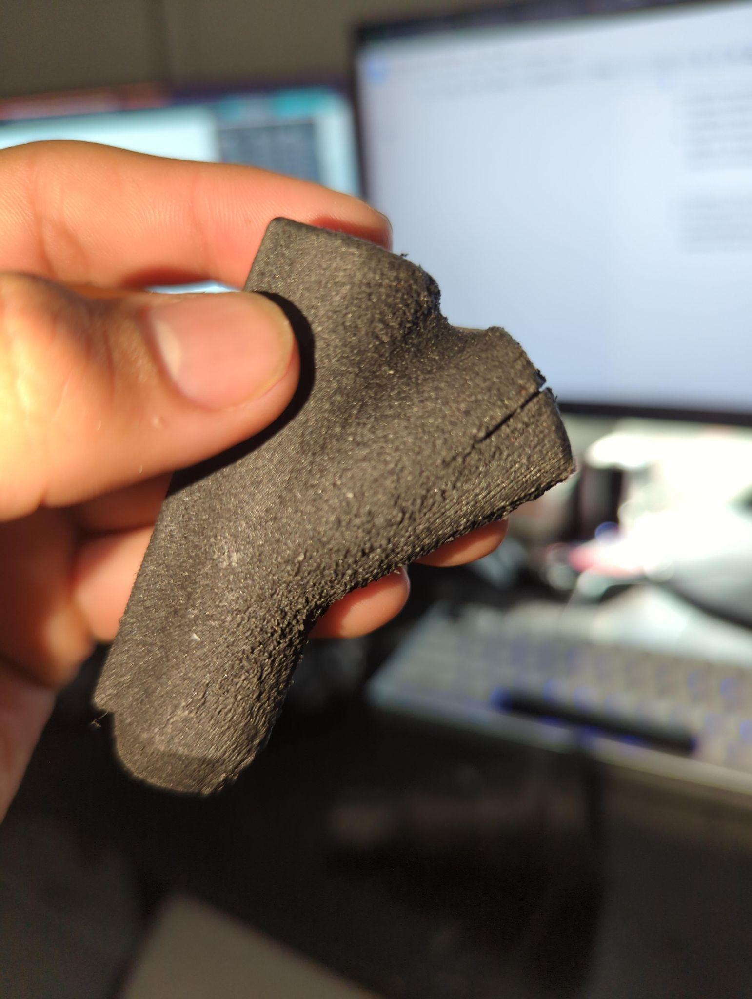
- Mid-print failures — PPA required higher chamber temperature for inter-layer crystal diffusion; learned and resolved
- Polymer creep under heat soak with Nylon-612 — clamp installation deformed nozzle body
- ¼" liquid inlets snapping under installation torque — print orientation issue
- Orientation fix altered pressure dynamics — vacuum insufficient for atomization
- Thread orientation offset when fixing inlet angle — threads sheared on first installation
Learned
- PPA-CF requires preheating protocol — defined and adopted
- Clamp installation superior to threads for engine bay reliability
- Print orientation, pressure dynamics, and structural integrity must be solved simultaneously — not sequentially
Fourth Generation — Final Production Spec
Resolution
- Polythalamide-CF layer adhesion resolved via preheating — ¼ and ½" variants both adequate strength
- Clamp securing replaces threads — universal installation, no thread failure modes
- Polymer creep eliminated — PPA-CF with preheating protocol
- Print orientation reverted to Gen 3 — structural optimum confirmed
- Nanoceramic impregnation seals all micro-pore pathways
- Mechanical air regulator — no electrical control required at nozzle
Validated
- 4+ weeks engine bay heat soak — no deformation, no failure
- PWM pump dependency fully eliminated
- Manufacturing cost: ~$3 vs. $100–130 retail
- Atomization quality superior to pump-driven equivalents at target flow range
- Single solenoid control — installation simplified to one wire
STATUS: CORE METHOD · REV: A2.0
The Development Philosophy
Both products were designed under the same constraint: use the manufacturing method to achieve what the manufacturing method makes uniquely possible. A machined catch can is limited by what a cutting tool can reach. An additively manufactured one isn't. That's not a minor distinction — it's the entire design space.
Every generation documented here represents a real failure that produced real data. The development logs above are not marketing copy. They are the actual record of what broke, why it broke, and what was changed. That record is the product's credibility.
Sanchez Performance builds to order from Austin, Texas. Serious inquiries only.
products@sanchezlabs.us